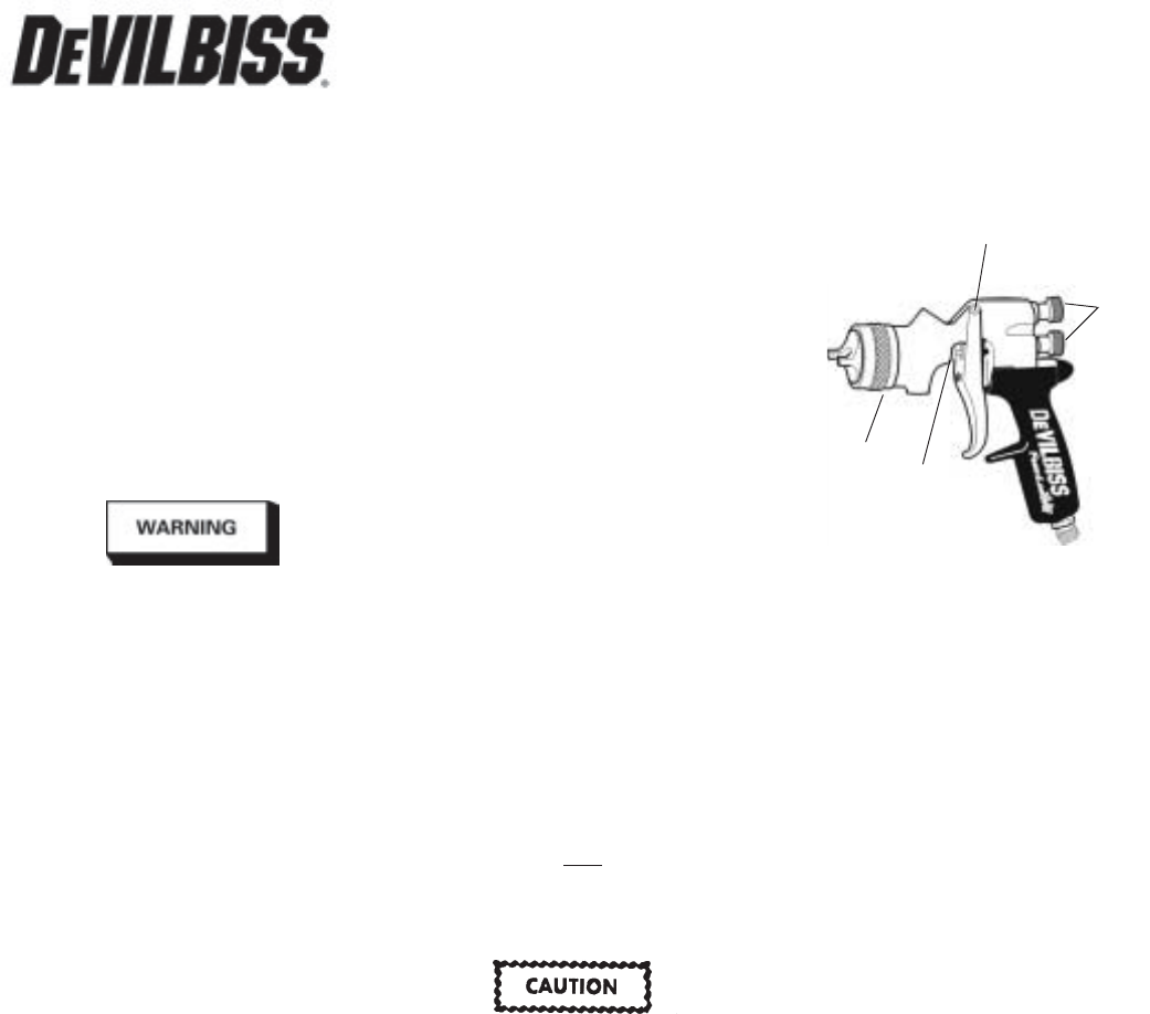
A. Trigger Points
B. Packing
C. Adjusting Valves
D. Baffle Threads
DESCRIPTION - 120175 (
GFC-502
)
This 32 oz. cup is designed to be used with
or without the DeVilbiss disposable cup
liner. The cup liner allows painting in any
position and simplifies clean up.
This gravity feed cup is designed to work
with the FLG, GFG and GFHV gravity feed
spray guns. The cup is constructed from
durable aluminum to provide trouble-free
operation. The cup insert is electroless nickel
plated brass. The disposable cup lid is recy-
clable and is constructed with recycled poly-
ethylene. The lid has a unique drip check to
prevent paint from dripping out of the vent
in the lid.
ASSEMBLY OF CUP TO GUN
1. Remove one of the cup gaskets (26)
from the poly bag.
2. Place this gasket in the fluid inlet of the
gun body. See drawing on page 4.
3. Store remaining cup gaskets in safe
place for future use.
4. Place filter (25) in cup outlet at this time
if desired. See drawing on page 4.
5. Assemble cup to gun and tighten hand
tight.
FILLING WITH PAINT
Fill the cup with paint to the full mark.
Do not overfill.
INSTALLING THE LID
Place plastic lid on the top of the cup, and
push in the center of the lid to assemble
lid. Fold vent cap and push onto center
portion of lid (if vent cap is not already
assembled).
SERVICE BULLETIN
SB-2-605-F
Replaces SB-2-605-E
Gun Repair Kit FLG-480
IMPORTANT: Before using this equip-
ment, read all safety precautions
on page 2 and instructions. Keep for
future use.
DESCRIPTION
The FLG-615 and FLG-635 are light weight,
çµneral purpose gravity feed spray guns
for both conventional and HVLP spraying
applications suitable for use with a wide
variety of common coating materials.
Halogenated hydrocarbon sol-
vents - for example; 1, 1, 1-
trichloroethane and methylene
chloride - can chemically react with
the aluminum in this gun and cause
an explosion hazard. Read the la-
bel or data sheet for the material
you intend to spray. Do not use
spray materials containing these
solvents with this spray gun.
IMPORTANT: This gun may be used with
most common coating and finishing mate-
rials. It is designed for use with mildly
corrosive and non-abrasive materials. If
used with other high corrosive or abrasive
materials, it must be expected that fre-
quent and thorough cleaning will be re-
quired and the necessity for replacement of
parts will be increased.
OPERATION
Strain material thru 60 or 90 mesh screen.
Model FLG-615:
The No. 1 (conventional) air cap requires an
air supply at the gun inlet of approximately
45 psi, measured with the trigger pulled.
Model FLG-635:
The No. 3 (HVLP) air cap requires an air
supply at the gun inlet of 23 psi max.,
measured with the trigger pulled.
This gun was manufactured to provide
maximum transfer efficiency by limiting air
cap pressure to 10 psi (complies with rules
issued by SCAQMD and other air quality
authorities).
This gun wil produce approximately 10 psi
cap pressure at 23 psi gun inlet pressure, as
measured at the gun inlet. An air cap test kit
(see Accessories) should be used to insure
10 psi cap pressure is not exceeded.
FLG-615 AND FLG-635 SPRAY GUN AND GFC-502 CUP
Adjust inlet air pressure to provide a uni-
form dispersion of atomized paint through-
out the pattern. Keep air pressure as low as
possible to minimize bounce - back and
overspray. Excessive pressure will result in
split spray patterns. Inadequate pressures
will cause heavy centered patterns and
poor atomization. See Spray Gun Guide,
SB-2-001, which is available upon request,
for details concerning set up of spray guns.
PREVENTIVE MAINTENANCE
To clean air cap and fluid tip, brush exterior
with a stiff bristle brush. If necessary to
clean cap holes, use a broom straw or tooth-
pick if possible. If a wire or hard instrument
is used, extreme care must be used to pre-
vent scratching or burring of the holes which
will cause a distorted spray pattern.
To clean fluid passages, remove excess ma-
terial at source, then flush with a suitable
solvent. Wipe gun exterior with a solvent
dampened cloth. Never completely immerse
in solvent as this is detrimental to the lubri-
cants and packings.
Note
When replacing the fluid tip or fluid
needle, replace
both at the same
time. Using worn parts can cause
fluid leakage. Using the supplied
fluid tip tool (16), tighten fluid tip
hand tight.
To prevent damage to the fluid tip
(3) or fluid needle (6), be sure to
either 1) pull the trigger and hold
while tightening or loosening the
fluid tip or 2) remove fluid needle
adjusting screw (15) to relieve
spring pressure against needle
collar.
Spray Gun Lubrication
Daily, apply a drop of SSL-10 spray gun lube
at trigger bearing stud (11) and the stem of
the air valve (17) where it enters the air
valve assembly (22). The shank of the fluid
needle (6) where it enters the packing nut (8)
should also be oiled. The fluid needle pack-
ing (9) should be kept soft and pliable by
periodic lubrication. Make sure the baffle (5)
and retaining ring (1) threads are clean and
free of foreign matter. Before assembling
retaining ring to baffle, clean the threads
thoroughly, then add two drops of SSL-10
spray gun lube to threads. The fluid needle
spring (14) and air valve spring (18) should
be coated with a very light grease, making
sure that any excess grease will not clog the
air passages. For best results, lubricate the
points indicated, daily.
Products shown covered by following U.S. Patents; D386,654 & 5,582,350.
A
B
C
D
(Continued on page 4)


 (32 pages)
 (34 pages)
 Manymanuals.com
 Manymanuals.de
 Manymanuals.fr
 Manymanuals.it
 Manymanuals.pl
 Manymanuals.cz
 Manymanuals.es
 Manymanuals-pt.com
Comments to this Manuals